space-invaders
A simple video game on an FPGA
For this project, I implemented a version of the arcade game Space Invaders in Verilog using a Nexys3 Spartan 6 FPGA board. The game consists of:
- A player, which can be moved left and right across the bottom of the screen
- A laser, which can be shot upwards from the player's laser base
- A 5x11 grid of invaders that continuously moves left and right across the middle of the screen
- 3 missiles, which the invaders somewhat randomly shoot down towards the player
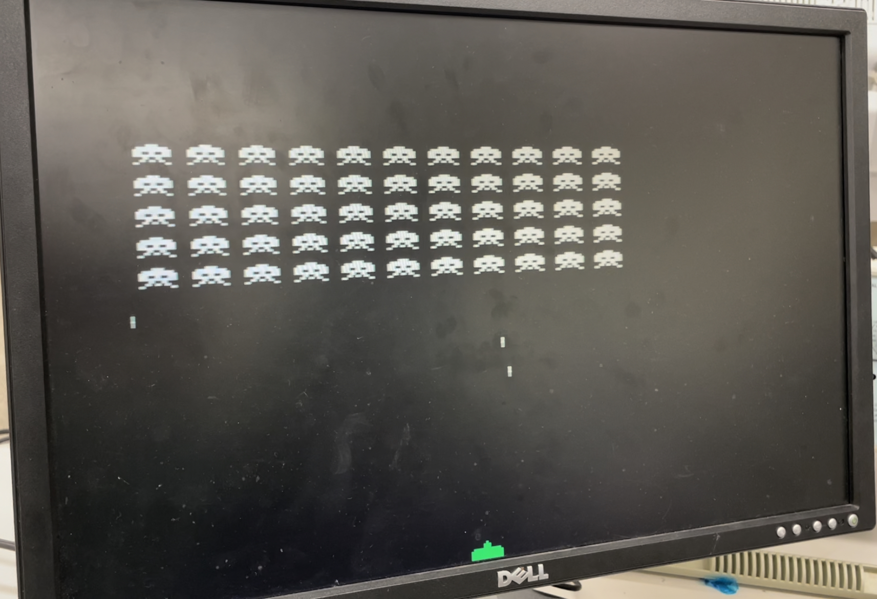
Initial game state
The gameplay is as follows:
- The player starts with 3 lives. Each time the player is hit by a missile, one life is lost. The player loses when no more lives remain.
- The player's score is increased by one each time an invader is shot down. The player wins the game when no more invaders remain.
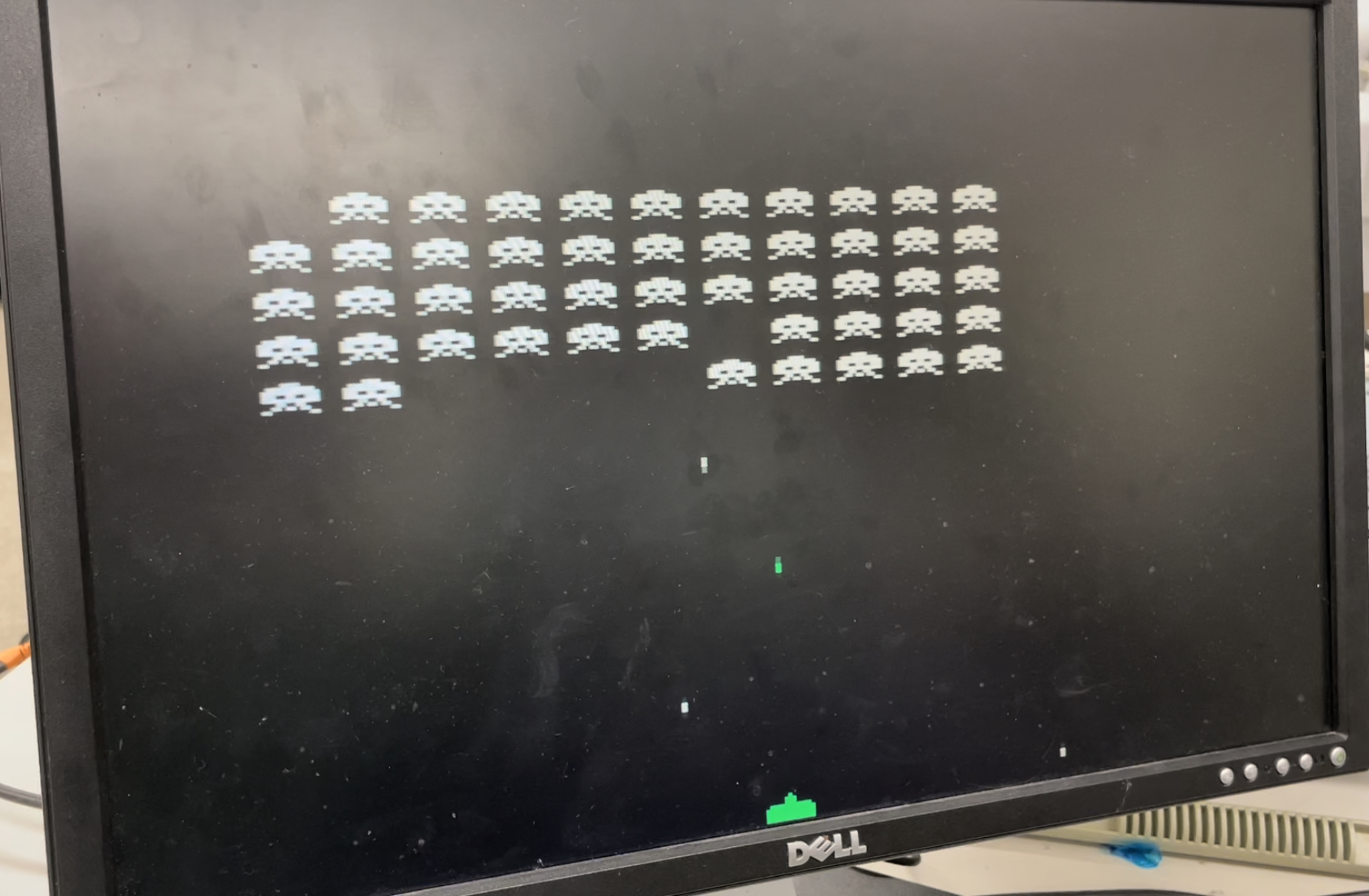
Game during play
And the game uses the following hardware:
- Left and right buttons for player movement
- Shoot button for the player's laser
- Reset button that returns the game to its initial state at any point
- 3 seven-segment displays for the player's lives and score count
- VGA output to display the game on an external monitor
VGA Implementation
The VGA display has a resolution of 640x480 pixels and is driven by a 25 MHz pixel clock, giving it a refresh rate of approximately 60 Hz. It supports 8-bit color. Much of the display code is based on this tutorial. My implementation for the following modules can be found here.
VGA Timings Module
Below is a diagram of the display timings and corresponding screen coordinates. Signed coordinates are used here so that the blanking interval can occur before the active drawing area, but the first pixel of the active drawing area will still be (0,0) so we don’t need to worry about offsetting all of the other coordinates. We want the blanking interval to occur before the active drawing area so that any setup for drawing sprites at the edge of the screen, which needs to occur before the first sprite pixel is drawn, can still occur during the same frame as the frame the sprite is actually drawn in.
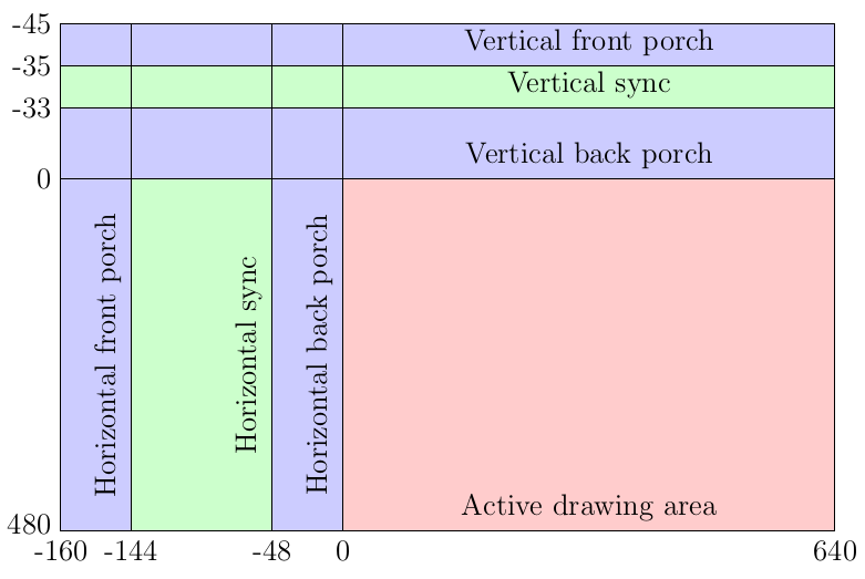
VGA signal timings
This module outputs the horizontal and vertical sync signals, as well as a frame signal that indicates the start of the blanking interval, when we can move our sprites (so that we don't run into screen tearing) and check the collision signals (e.g. for keeping track of the player's lives and score, so that collisions aren't counted more than once). It also outputs a data enable signal that is high during the active drawing period, and the current horizontal and vertical screen coordinates.
Draw Sprite Module
This module draws a single sprite from a bitmap that can be scaled vertically and horizontally by the same constant. The sprite is represented as a 2d array, which is loaded from the bitmap. Horizontal and vertical variables are maintained for addresses within the sprite bitmap of the sprite pixel currently being drawn, and the output drawing signal is set to high if the sprite is currently being drawn (state = DRAW) and the bit at the current address is high. This is implemented as a finite-state machine, which can be seen below.
State diagram for sprite drawing
Signals:
- start: Signals when to start the sprite drawing
- pixel_x: Current horizontal screen coordinate
- spr_x: Top left x coordinate of the sprite
- x: Horizontal address within sprite bitmap
- y: Vertical address within sprite bitmap
Draw Sprite Row Module
This module draws a row of 11 sprites from a single bitmap that can be scaled vertically and horizontally by the same constant, and allows for individual sprites in the row to be visible or hidden. Its logic is very similar to the previous module, with the addition of a START_SPRITE state between AWAIT_POS and DRAW, which increments a counter indicating the position of the sprite currently being drawn, and checks to see if the next sprite should be drawn or hidden.
VGA Controller Module
This module receives the positions of everything that needs to be drawn on the screen and handles drawing them or starting the correct drawing modules, outputting the correct 8-bit color pixel. It also blinks the player 3 times when it has been hit by a missile, and detects collisions between the player and the missiles or the invaders and the laser by setting the corresponding collision signal when the relevant drawing signals are high at the same time.
Button Debouncing
Physical switches and buttons can cause small vibrations when they are pressed or flipped, resulting in small voltage fluctuations that can appear as multiple button presses within a very short amount of time, rather than as a single press. To solve this issue, we can sample the button state at a slower frequency, and only report the button as being pressed when it can maintain the same state for some period of time longer than the period of an average voltage fluctuation.
To implement button debouncing, I used a 100 Hz clock to sample the button signals. These samples are accumulated in a 3-bit register for each button, so that each clock cycle, a new sample is added to the left-hand side of the register and the other bits are shifted right by one bit, discarding the least significant bit. The 2 rightmost bits are used to detect a change in button state (0 then 1 means the button went from off to on, 1 then 0 means the button went from on to off). The third bit is for debouncing - since the sampling frequency is 100 Hz, the signal is required to stay high or low for at least 10 ms before we can conclude that the button is actually on or off, and that the high/low signal is not just the result of a fluctuation.
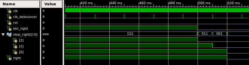
Waveforms from Xilinx ISE Simulator:
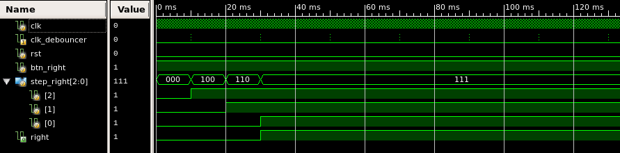
Debouncing a button press
Debouncing a button de-press
Above, clk_debouncer is a 100 Hz clock, btn_right is the signal from the button we are debouncing, step_right is the 3-bit sampling register, and right is the debounced button signal. Code for this debouncing logic can be found here.